


You need to find minimum radius of rotor (r) needed as
per following requirements:
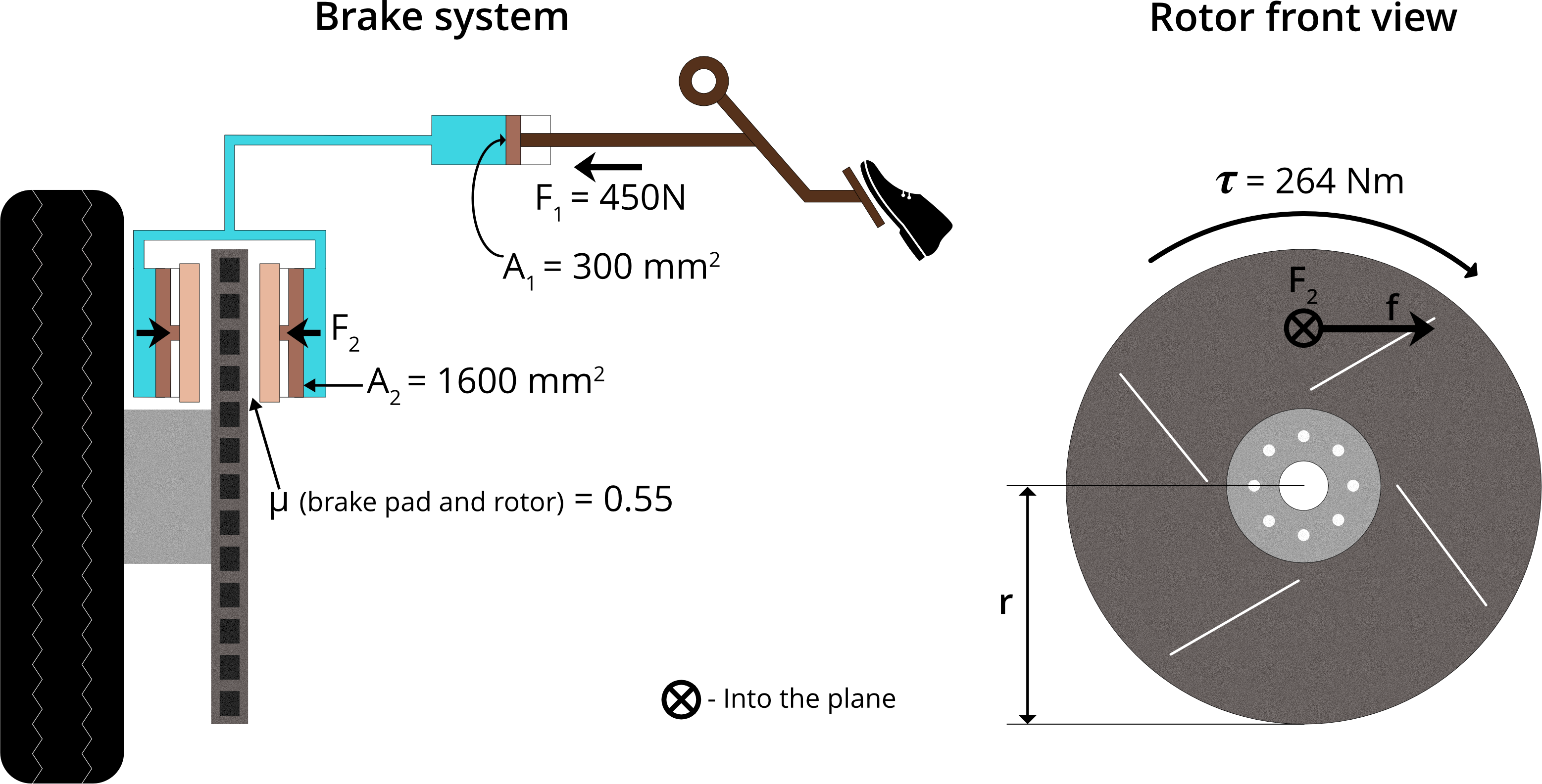
When driver presses the pedal, consider force exerted on master cylinder (F1) = 450 N
We will use our standard master and slave cylinders
where cross-sectional area of
Master cylinder (A1) = 300 mm2
Slave cylinder (A2) = 1600 mm2
Rotor material will be cast iron, so friction coefficient
between rotor and brake pad (µ) = 0.55
To stop car in desired way, minimum torque required
from friction between brake pads and rotor (τ) = 264 Nm
(Assume brake pads are very small compared to rotor
and close to rim of rotor to use radius of rotor “r” in
torque formula.)
Start Working
You will now begin working on the rotor radius calculation. This assignment has a duration of 10 minutes.
 Back
Back How to find rotor radius?

When brake pads press against the rotor they each exert force “F2” normal to the circular face of rotor and friction force “f” parallel to its circular face. Friction force produces a torque “t” in the opposite direction of rotor’s rotation causing it to stop.
Step 1
Find force “F2” exerted by fluid on piston of each slave cylinder, using Pascal’s
law and given “F1”, “A1”, “A2”
Step 2
Find friction force “f” exerted by each brake pad on rotor, using “F2” and given “µ”
Step 3
Find “r”, using total friction force on rotor and given “τ”

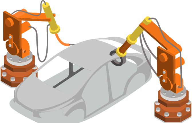
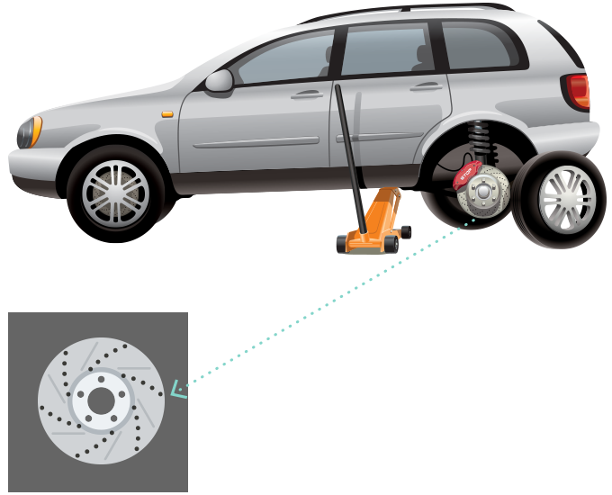
 About Brake System
  Hint
Hint
Step 1
By Pascal’s Law
F1/A1 = F2/A2
Step 2
Friction force exerted by each brake pad on the rotor
f = μ x F2
Step 3
Torque on the rotor due to friction from the two brake pads
Ï„ = r x total friction force on the rotor
= r x 2f
 Hint
Hint
Friction force on rotor by single brake pad (f) = μ x F2
Total friction force on rotor (fT) = 2f
(as there are two brake pads, one on both sides of the rotor)
Time is up!
This assignment could have been solved within 10 minutes. You can still continue to work on it, though deadlines are important in industry.